These have been sold and moved to Georgia I
thought I'd do this one in a journal format. Part
1 -- 18 APR 2004 Background Line arrays are a current rage in the DIY community. Based on my observation, they seem to fall into two basic categories: cheap driver experiments and massive high end units. After reading up on Jim Griffin's paper and looking at some of the available designs, I decided I would try my own version. Being a middle of the road kind of guy, I wanted a high quality product without spending a fortune on drivers. With all of my old-age maladies, the design needed to be small enough to move (and possibly ship). It also had to be flexible enough to experiment with different tweeter configurations. The major challenge would be finding the right woofers. I wanted to use a single tweeter (or a few tweeters) rather than a line of ribbons -- to cut costs and minimize mass. With multiple woofers, the gain in efficiency almost necessitates the use of multiple tweeters. Based on theory, I wanted a smaller driver (4-5 inch) to minimize comb filtering effects and allow for some flexibility in crossover frequency. In a perfect world, this driver would be inexpensive, sonically capable, shielded (for HT compatibility), and relatively inefficient. Woofer Selection and Box Design (April 2004)
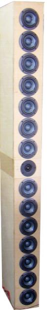
The next consideration was: How many per side? Based on designing a single woofer, I chose 5 liters per driver, vented, tuned to 64 hz. This would be a slightly larger than optimal box, but, I felt it would be easier to add "fill" if necessary. Using a simple spreadsheet, I set out to find the number of drivers and predicted efficiency. I experimented with a variety of wiring combinations in an effort to come up with a reasonable impedance and the lowest efficiency .I wanted to match with a single tweeter if possible. I finally chose to use 14 drivers per side wired in a 4-3-3-4 configuration. This gave a nominal impedance of 10 ohms and predicted efficiency of 98 dB. With smaller gauge coils and baffle step compensation, I reasoned that 94 dB would be a likely -- making a single tweeter possible.
The box is split in two. By building each half separately, I could more easily move the pieces, and swap tweeter configurations easily. If I can't find a single tweeter efficient enough to match the woofers, I can simply bolt the two halves together and side mount the tweeter array. This split box would also enable shipping the arrays by common carrier. Since a single 4x8 sheet of veneer will not cover both speakers, the split design will allow more flexible finishing options. The 7 1/8" width will allow adequate room for 3/4" roundover along the vertical edges and enough room for grills (if SWMBO requires them.) With 7 drivers per half, I would up with a nominal box size of 35 liters. For measuring purposes, I chose to build only a single box -- no reason to do both if it's just an experiment (too much routing!). In the tall picture above, you can see the two halves, with the first tweeter insert. While not my first choice, the 4-ohm Vifa DX25 is reputed to have 93-94 db sensitivity. (The 8-Ohm Morel DMS 37 would be my first choice). However, since I had two on hand I reasoned that I could measure the DX-25 tweeter at the same power levels as the woofers. This would at least tell me whether the single tweeter idea is feasible. Initial Measurements (18 APR 2004) Calm 75 degree days in the Arizona desert will soon be very scarce, so I decided to try some measurements to check on relative SPL levels and confirm the theoretical impedance checks. Only one cabinet was properly sealed. I threw some foam inside, duct taped the back onto the second box and erected the array. Using a couple of brooms (and more duct tape) to stabilize the tower. (SWMBO came outside, took one look, and walked away muttering something about lawyers...) In theory, using a single tweeter (point source) with the line source would result in different apparent volume level. Each time the distance doubles, a nearfield line source should lose 3dB -- a point source should lose 6dB. So I chose to set up the measurements at a typical listening distance. I erected the array on the edge of my garage slab, and positioned the mike about 11 feet away (most likely listening distance). I just eyeballed the height and relative angle to coincide with the tweeter. After the usual 20 minutes of fiddling and calibration, I finally got a set of measurements. CLICK HERE TO SEE INITIAL MEASUREMENT PAGE The impedance curves looked pretty good and matched up with predictions for the array -- suggesting that I had wired things correctly. The DB scale is obviously not correct, but I used the same power level for both the tweeter and woofer. The DX-25 looked about right. The slight rise in the 5000 range is most likely edge diffraction. It can be treated in the crossover (if necessary) and will be much smaller when the edges are rounded. (Note: 1/3 octave smoothing is used) The woofers look a bit ragged (1/12 octave smoothing) but I wanted to see the cancellation effects from the multiple woofers. The effect is pretty clear out at 5000-10000 Hz. The downward slope from about 100 to 500 is likely a combination of baffle step and ground reflections. (Note the longer measurement gate -- 50 ms) More troubling is the peak from 600 to 1000. It's possible that part of this is pipe resonance from a poorly damped cabinet. I also noticed that my duct tape seal didn't hold up. The natural rolloff in the 2000 range suggests that a fairly low crossover point will be used. The third panel is most encouraging. With all drivers wired together, in parallel, it appears that a single tweeter is viable. Assuming that box resonances are responsible for the peaks in the 500-2000 range, this looks like a doable deal. Soooo...time to order the Morels. Now I have to figure out how to model the woofer geometry in LspCad -- and finish damping/bracing the cabinets, do the roundovers, find time ... |
||||||||||||
|
Second Measurement Set 23 APR 2004 After a phone call with Rick Craig at Selah Audio it was apparent that measuring one of these beasts is a less than exact science. Rick and I both use LspCad. Normally for an MTM design, a single woofer is measured along with the tweeter. Each of the woofers is then located on the box front so the program can accurately model phase and lobing effects. With seven drivers on each half, where is the geometric location of the acoustic center? Rick suggested modeling as a simple TM with coincident acoustic centers. Based on his experience, he recommended careful alignment of the measurement mike on the tweeter center -- to minimize any cancellation/reinforcement (CA/RE) from woofer interaction. He suggested the peak areas MAY be artifacts of the CA/RE -- and that small changes in microphone position will result in large measurement changes. Carrying this logic a bit further, could one look at the array as a 2.5 or maybe a 3 way? The resistance tapering introduced to reduce "sound bloom" suggests that outer drivers should be a bit weaker in SPL. Jim Griffin mentions the possibility of treating those peripheral drivers with a separate crossover. If one rolled off those outside 8 drivers on a steeper slope than the middle 6 drivers, could you use that compensate for baffle step and control the bloom? Seems like something worth checking out.
After erecting the cabinets, I hit on easy way to align the microphone with the tweeter center. First I set the cabinet plumb and level. Next, I set a chalk line on the ground perpendicular to the baffle. About 2.5 meters away, I set up a piece of plywood with a tape measure hanging over the front. Next, I retrieved a small laser pointer I use in the classroom. I carefully taped it to my 4 foot carpenters level. Now I simply, placed the edge of the level on the tweeter axis, aimed it at the tape, and read off the height. Instant laser level! After a couple of hours, I had a new set of measurements. I went ahead and split the woofers into the "Inner 6" and "Outer 8" based on my wiring. I noticed the peak centered at 700 hz is still present. It seems to be more pronounced in the Outer 8, less so with the Inner 6. I have no idea why. Bogus Measurements and Initial Xover 25 APR 04 After spending time trying to model my second set of measurements, I was concerned that the Morels couldn't play loud enough. The all driver spl looked like I would have more than enough headroom. But when I loaded the driver specs, it looked grim. I went ahead and designed a simple crossover to try out. If the Morel wouldn't play loud enough, I would have to do a major revision of the design -- or possibly scrap it altogether. With the test Xover, I wired up the pieces, slid in the test CD, and fired up the prototype. Much to my surprise, (and delight) I wound up with a 4 ohm series resistor on the Morel. So, something was funky with my last set of measurements. I traced it to a bad jack on my sound card. After fixing things, I measured TBLA again. Listening to the quick and dirty crossover, the image is definitely different than the traditional TM. I liked the DMS 37 a lot, not as beamy as I had feared, very smooth and warm. The box sounded a bit boomy, so I tried plugging the vents, this smoothed out the response quite a bit. The crossover wasn't bad, but wasn't quite right. Some phasing/sibilance issues and overly subdued female vocals. I will also experiment with stuffing and bracing. CLICK HERE FOR REVISED "FINAL" MEASUREMENTSThe
new measurements looked much more reasonable with respect to SPL
and tweeter responses the high end tail-off noticed earlier. I went
back to LspCad and introduced the new measures. By using the "Combined
Array SPL2" as a target curve, I was able to match the individual
driver responses to the combined curves. An encouraging sign for
sure. To get this match, I had to add 5db to my measured response for the Morel. I'm not sure why this was necessary, but it explains the need for padding down the Morel in the first design. Using the basic topology of the first crossover, I was able to construct a fairly smooth TM crossover. The gentle slope from low to high is intentional, I find it easier on my ears.
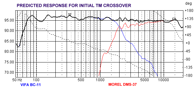
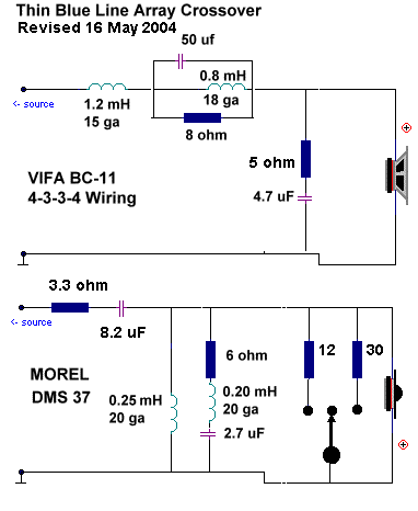
After three tries, I finally hit on a crossover design that seems to work well (or at least serve as a basis for tweaking). I had to cobble up coils and caps from supplies on hand, so the prototype looks pretty gross. Click here for Initial Crossover With a driver spacing of less than 5 inches, I needed to keep the crossover under 2800 Hz to minimize lobing effects. With the 2000 Hz point, the transition from woofer to tweeter seems fairly seamless. Even though I have only one box completed, I sat down in the garage and listened for about an hour. Overall, I liked what I heard. Bass is clearly available. Good slam and attack -- though just to the mid 60s. (I would have no trouble living with these in standalone mode) A bit of box resonance is noticeable so more damping and bracing is in order. I will try light stuffing with dacron and a bit more foam. The Morel is lovely. While carrying most of the 2K+ information, it reproduces highs effortlessly with very good dispersion. I ran it a bit hotter than I usually do, but never felt like I had to turn the volume down. There is a little bit of a sweet spot, but off axis is quite clear and clean. Moving from sitting to standing brings the image with you. Great female vocals, piano, and horns. Male vocals seem a wee bit subdued. I can't say much about imaging from a single channel. Overall, I'm very happy with the sound, and I'm certain this combo can be tweaked into submission. The RLC leg in the tweeter allows some shaping of response in the 3-6000 range (diffraction effects). With the parallel resonance filter (for the 500-800 peaks) and the zoebel, the woofer response can be formed. Impedance drops to a low 6.6 ohms at 2000 Hz -- so no problem driving the beast. Well, I'm out of play time for awhile. I need to build the other two box halves, design a mechanical coupling system, and a base. With temps already in the 90's, my shop time will be limited. So until I have working pair, there won't be much to report for awhile. I'll update when I get there. I finally got out to the garage to put together a revised crossover that addresses a few of the limitations of the first pass and uses single coils and caps. Changing the primary inductor to 1.2 seems to be the best balance so far. The move to 15ga also slightly increases sensitivity. With minor revisions to the pseudo zoebel and a lower cap on the tweeter, male vocals are clearer, and the 2000 hz area is slightly depressed. (A bit of BBC dip) Crossover is now about 2200 hz. Click Here for Crossover 2 With this topology, most of the shaping is best done with the woofer zoebel and the resonance filter on the tweeter side. With the padding resistor ahead of the tweeter circuit, changes there affect both volume and shape of the tweeter curve. The advantage is a smoother impedance profile. With temps here approaching 100, I need to work in the mornings. Hopefully the next entry will work with a stereo pair. I learned something about Baltic Birch. Don't cut it and leave it leaning. Warp city. (It might have something to do with climate changes from northern Europe to Southern Arizona.) I was able to finish the second set of boxes with lots of biscuits and clamps. I had used hurricane nuts to allow for removal of back panels. Don't cross thread those babies! They hold great but can be pushed out. I'm still wrestling with how I will attach all three sections to allow easy breakdown and reassembly.
I played a bit more and revised a bit. I restored the 8.2 uF cap in the tweeter circuit to bring the xover point closer to 2000. With some shaping of the zoebel, things looked good again. I came up with an easy way to experiment with tweeter padding. I added two shunt resistors just ahead of the tweeter. Using a SPDT switch with center off, I can now simply flip the switch to change padding. I will probably leave this in the final design with a cup. I tried using a conventional L-Pad, but the resonance trap really needs the resistor to stay at the front of the circuit to maintain the shape of the tweeter response. The switch allows about 1.5 dB of adjustment.
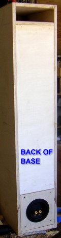
I chose to use 3/4 stock for the base plate on the second set of boxes and to glue in the back for additional stiffness. I did set up a removable insert for the terminal cup with hurricane nuts. This should allow me to change the crossover easily. The large cup allows use of the SPDT micro switch for selective tweeter padding. I just drilled a hole in the cup body. I wrestled with methods to attractively attach the three pieces. I built a tweeter insert choosing to laminate a second layer of 1/2" plywood. After discarding the use of long bolts and various knock down fittings, I talked to my neighbor and had him weld up four U shaped steel straps. He welded 1/4" bolts thru the top of the strap. I mounted these inside the tweeter boxes with #10 machine screws and nuts.
The down side of this method is pre finishing. I will put a chamfer on the matching edges to hide any misalignment, but I will need to veneer the big boxes before final assembly (to get all of the final thickness issues hammered out.) I had considered using a 3/4" roundover on the vertical edges. After measuring, I figured out it would take two large sheets of veneer. The roundover would also make it virtually impossible to build SWMBO-approved grills. There just isn't enough space between woofer frames and the edge. As I may keep these, four dogs almost necessitates some driver protection. So the plan is now black, square-edge fronts with the remainder veneered. The tweeter box will be black all around -- to hide any misalignment. I may bite the bullet and try to do a one piece grill out of 3/8 or 1/4 MDF. |
 The
Thin Blue Line Array Project
The
Thin Blue Line Array Project
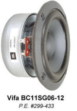 I
spent quite a bit of time looking for candidates and finally found
a good one - the Vifa BC11. As
a 12 ohm driver, with 86 db efficiency, this 4.5" seemed like
a great candidate. I had used a Vifa BC driver before (in my Onyx
design). I ordered four for a pair of MTMs (the Azurite). I found
this driver to be very sweet, capable of bass into the 60s, with
great high end extension. The tapered plastic flange meant minimal
routing, and they even come with integrated foam seals for mounting.
With volume pricing (21 per case), they are quite reasonable. I
decided this was the right driver.
I
spent quite a bit of time looking for candidates and finally found
a good one - the Vifa BC11. As
a 12 ohm driver, with 86 db efficiency, this 4.5" seemed like
a great candidate. I had used a Vifa BC driver before (in my Onyx
design). I ordered four for a pair of MTMs (the Azurite). I found
this driver to be very sweet, capable of bass into the 60s, with
great high end extension. The tapered plastic flange meant minimal
routing, and they even come with integrated foam seals for mounting.
With volume pricing (21 per case), they are quite reasonable. I
decided this was the right driver.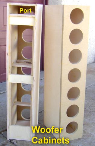 The
baffle is 3/4 MDF, remaining panels are 1/2" baltic birch --
to reduce weight. (I find 1/2" to be very capable for smaller
boxes with adequate bracing.) I also chose to build these
with removable back panels to make
it easier to wire (and rewire).
The
baffle is 3/4 MDF, remaining panels are 1/2" baltic birch --
to reduce weight. (I find 1/2" to be very capable for smaller
boxes with adequate bracing.) I also chose to build these
with removable back panels to make
it easier to wire (and rewire). 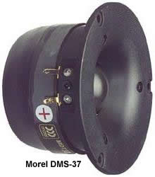 With
the arrival of the Morel DMS37 tweeters, I built a new tweeter insert;
finished damping/sealing of the second cabinet; and made a large
base for a stand. This would allow me to plumb and level the array
for the next set of measurements.
With
the arrival of the Morel DMS37 tweeters, I built a new tweeter insert;
finished damping/sealing of the second cabinet; and made a large
base for a stand. This would allow me to plumb and level the array
for the next set of measurements. 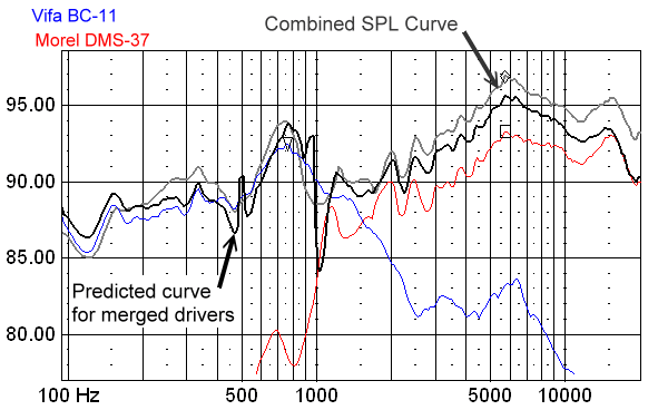
 After
listening to Crossover 2 for awhile, (during construction of my
After
listening to Crossover 2 for awhile, (during construction of my
 If
anyone ever tries to convince you to do a 2-3 piece cabinet, hit
'em with a hammer. Because of weight and size issues (baltic birch
comes in 5' x 5' sheets) my three piece cabinets are a real b*tch
to get aligned. If I were to do this again, I might choose to use
a 1/4" plywood skin, or hardwood sides.
If
anyone ever tries to convince you to do a 2-3 piece cabinet, hit
'em with a hammer. Because of weight and size issues (baltic birch
comes in 5' x 5' sheets) my three piece cabinets are a real b*tch
to get aligned. If I were to do this again, I might choose to use
a 1/4" plywood skin, or hardwood sides.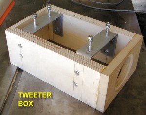 I
will glue the tweeter box to the base cabinets; drill holes in the
bottom plate of the top box; and tighten down the nuts through one
of the driver holes. Once I bondo the countersunk screw heads, and
set the nuts with locktite, The final look should be clean and permanent.
I
will glue the tweeter box to the base cabinets; drill holes in the
bottom plate of the top box; and tighten down the nuts through one
of the driver holes. Once I bondo the countersunk screw heads, and
set the nuts with locktite, The final look should be clean and permanent.