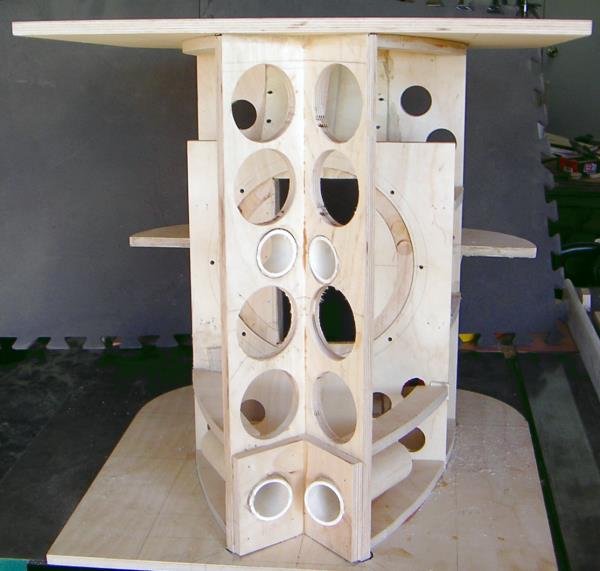
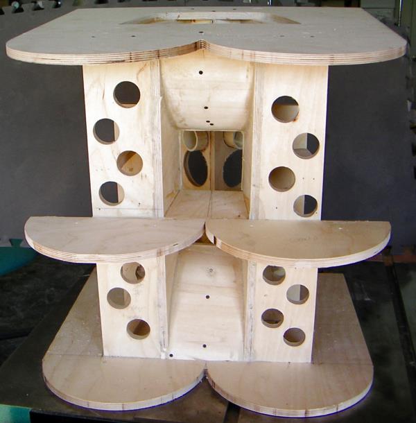
This front on shot shows the tweeter baffle and our alternative locations for the four ports in the tweeter baffle. (The plans call for slant drilling thru the sides) We changed our minds when we figured out the long ports would interfere with mounting the woofer. So we blocked the lower tweeter hole, and mounted the long ports there. The box is tuned to 50 hz. Not all measurements worked out perfectly.
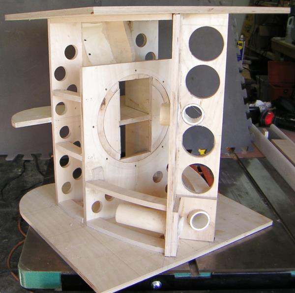
In this shot, you can see the baffle board and some of the bracing. The routed groove matches up with the surround on the Beta 10 -- to prevent the cone hitting the baffle. We should have done all the trim sanding/routing of the baffle slot before we glued the box together. We added more bracing before mounting the sides.
We used construction adhesive for bonding any sloppy joints. Titebond for the nice fits. 1" brads in my bradnailer worked great for the tight joints.
I used glue blocks to help with the assembly. We used hurricane nuts for mounting the driver. I always glue them around the flange. If we had rotated the driver a bit we would not had to cut slots for the machine screws to pass thru the hurricane nuts.
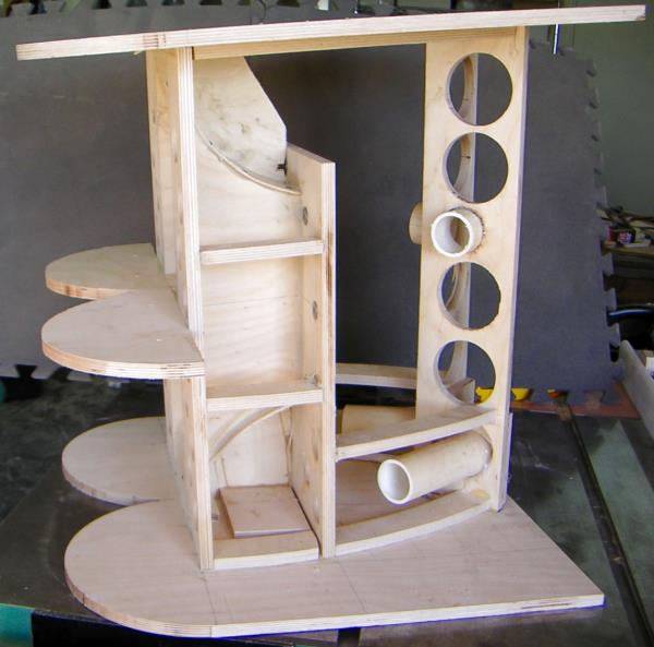
The initial curves on the flared horn, coming off the baffle use the 1/8" poplar. The plans call for 1/8 baltic birch. This was cheaper and easier to bend in our hot dry climate. I used square drive, 1" #6 trim head screws to mount. You can see the driver mounting hole on the top.
You can see the flare of the rearward horn. 4" at the baffle, 5" at the throat. Not clear in the plans. Those two semicircular braces made life difficult, I should have mounted them after I covered the sides. Lot's of angled cuts on this baby!
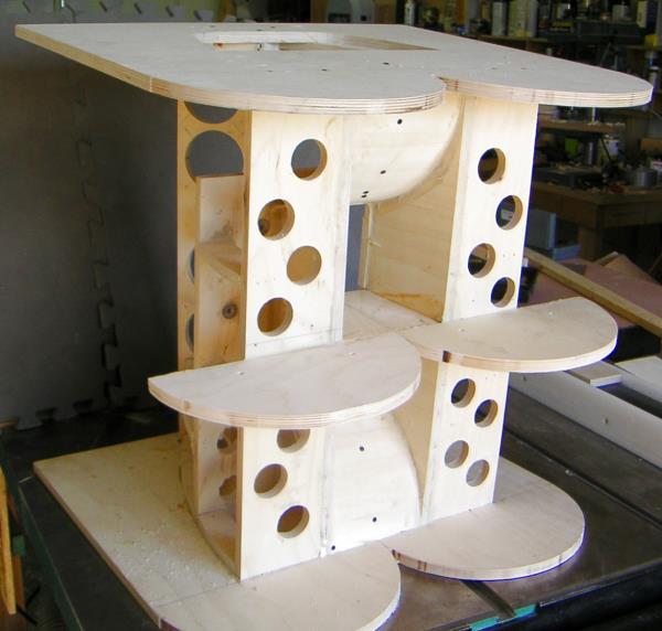
The top and bottom were cut with the Jasper jig and came out very clean. We used the top, and a flush trim bit to cut the two center braces.